Challenges in Aero Engine Performance Modeling

As is the case with every machinery, manufacturers want to improve their products. This is especially true for aero engines, where even a small improvement in fuel consumption can lead to an advantage on the market. But with any type of propulsion equipment, regulations also play an important role, specifically that certain noise levels or CO¬¬2 emissions should not be exceeded. These factors combine to make the process of developing and manufacturing an aero engine anything but simple. In today’s blog, we’ll take a look at these challenges in more detail and briefly touch upon development strategies to account for such challenges.
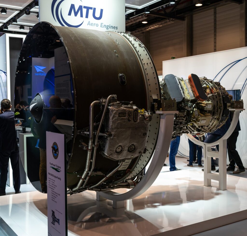
PW 1000G
Figure 1: BERLIN – APRIL 26, 2018: The stand of MTU Aero Engines and high-bypass geared turbofan engine family Pratt & Whitney PW1000G. Exhibition ILA Berlin Air Show 2018.

In general, engineers have two options to develop a better engine. The first is to create a completely new design, like implementing a geared turbofan, which takes a lot of time and research. An example of this is the PW1000G engine from Pratt and Whitney, which was in development during the late 1990s and had its first flight test in 2008 [1]. This approach is less common which is reflected by other manufacturers who are backing down from the idea of using geared turbofans due to weight and reliability concerns [2]. The second option and this is the common method, is to gradually improve existing engines. This however brings new challenges, because simply improving one engine component does not necessarily mean that part of the machine will work well together with the rest of the machine. Furthermore, the design process for aero engines is very time-consuming. A general overview is shown in Figure 1. The process starts with an assumption for certain performance characteristics, for example, efficiencies for a compressor. After that, a cycle analysis is performed where the design point and off-design behavior are determined. With the newly gained information, the design process of the single component takes place. Upon successful creation of the component which satisfies all requirements, the process moves to the test phase. In this phase, the designed machine will be evaluated through experimental testing or intensive CFD studies. Modifications will be made if necessary to reach the desired operating conditions. Since changes were made to the geometry, these changes need to be investigated in an additional cycle analysis to understand how they will affect the overall engine performance. This process repeats until a converged solution is found. Read More

Scaling and Trimming in Axial Compressors and Fans

Introduction

Despite the deepening understanding of the essence of gas-dynamic processes and the development of computational methods, simpler design methods such as scaling and trimming remain in demand in turbomachinery engineering. The main advantage of these approaches over design from scratch is simplicity and its inexpensive nature due to the small-time expenditure and lower demand from computational resources. Good predictive accuracy of the performance and efficiency of the resulting machines is based on the use of an existing machine with well-known characteristics as a prototype.

Conversely, using the prototype imposes restrictions on the use of scaling and trimming methods. It is almost impossible to get a new design with pressure and efficiency higher than that of the prototype. Also, in cases where it is required to obtain performance that is significantly different from the prototype, the inherent reliability of the original prediction may be insufficient.

Scaling Method

Easy to apply and general, valid, scaling laws are needed for design and application engineers. The scaling laws are needed for the purposes of:

  1. Predicting the full-scale performance machine from model test data obtained from a scaled machine
  2. Obtaining a family of machines with different performances on the basis of one well-tested machine

­

Experimental performance and efficiency testing on a full-size model of large machines such as fans to ventilate tunnels and mines or to move combustion air and smoke gas in power plants may be impractical due to the high energy costs and geometric limitations of the experimental stand. In these cases, a scale model is used. And although complete similarity is not maintained, for example, in terms of the Reynolds number, the correction factors in most cases are well known and the prediction accuracy is high.

The method involves the implementation of the flow path of the designed fan or compressor on a scale to the prototype. This means that all linear dimensions (e.g. diameters, blade chord, axial length, etc.) must be multiplied by the scaling factor (SF). The angular dimensions (e.g. blade angles at inlet and outlet, stagger angle, etc.) remain unchanged.

When scaling, it is assumed that parameters such as Pressure Ratio, circumferential velocity (U), and axial velocity (Cz) are equal for the designed machine and the prototype. Thus:

Trimming and Scaling Formula 1

The condition of equality of the Reynolds criteria is not ensured, since the designed compressor and the prototype do not have the same diameters of the rotor with the equality of other parameters that determine the number of Rew. This design guarantees the practical accuracy of the calculated characteristics, provided that the gas movement in the flow path is turbulent. It is known that for “physical” values of the Reynolds numbers

Trimming and Scaling Formula 2

the flow remains turbulent and the inequality of the Reynolds numbers of the designed compressor and the prototype has little effect on the gas-dynamic characteristics.

To determine the efficiency of low-pressure fans, a well-known formula is usually used:

Trimming and Scaling Formula 3

An example of obtaining a stage of an axial compressor by the scaling method is shown in Figure 1.

Figure 1 - Axial Compressor Stage Scaling
Figure 1 – Axial Compressor Stage Scaling

The disadvantages of the scaling method include the need to change the rotor speed. This can be relevant for industrial installations, where the rotation speed is often limited and tied to the frequency of the electrical network current. Additionally, the need to change the overall dimensions can be a limiting factor, especially if it is necessary to increase productivity significantly, and the installation location for the turbomachine is limited. In some cases, maintaining full geometric similarity is impossible for technological or constructive reasons. For example, the minimum value of the tip clearance may be limited by the operating conditions of the rotor (not touching the rotor against the housing) or the impossibility of obtaining a small clearance if the scaling is carried out from a large prototype to a small model.

Read More

Initial Sizing of Centrifugal Fans

Centrifugal fans are a type of turbomachine equipment widely used in all kinds of modern and domestic life. Centrifugal fans were developed as highly efficient machines, and the design is still based on various empirical and semi-empirical rules proposed by fan designers. Due to these various rules, there are different methodologies used to design impellers and other components.

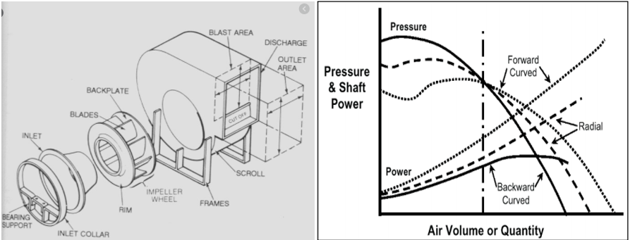
Centrifugal fans consist of an impeller in a casing with a spirally shaped contour, shown in Figure 1 (left side). The air enters the impeller in an axial direction and is discharged at the impeller’s outer periphery. The airflow moves along the centrifugal direction (or radial direction). Centrifugal fans can generate relatively high pressures, as compared with axial flow fans. For axial flow fans, the pressure rise is small, about be few inches of water.

Radial Fan and Static Pressure
Figure 1 Radial Fan and Static Pressure, Shaft Power V/s Volume Flow Curves for Different
Types of Blades

Generally, centrifugal fans have three types of blades: forward blade, backward blade, and radial blade. The characteristic curve of these three kinds of centrifugal fans is shown on the right side in Figure 1.

Sizing Using Cordier Diagram

Centrifugal fans (most turbomachines) can be classified based on specific speed (Ns) and specific diameters (Ds) as shown in Figure 2. Specific speed is a criterion at which a fan of unspecified diameter would run to give unit volume flow and pressure. The correlation for a specific speed and specific diameter can be seen here:

Pump Formula

where, ‘N’ is rotational speed (RPM), ‘Q’ is flow rate (ft3/sec), ‘H’ is head (ft), ‘D’ is diameter (ft) Read More

Considerations for Electric Aircraft Fan Design

Due to concerns about air travel’s impact on climate change, research and development into electric aircraft has been ongoing for several years. Within the last decade several startups as well as larger corporations have been developing electric or hybrid electric aircraft (Ros, 2017). The ultimate goal is to Conduct long (>500 miles), full-electric commercial flights with large aircrafts capable of carrying 100’s of passengers, but this will require at least 5-10 more years of development. Luckily, smaller electric aircraft designed for short-range flights (<500 miles) with anywhere from 1-20 passengers have already been tested successfully utilizing electric batteries, a hybrid-electric system and even a hydrogen fuel cell.  With these advances, emission-free air travel is closer than you think.

Electric Aircraft

Examples of full-electric aircraft designs include the Airbus E-Fan 1.0 and E-Fan 1.1 (Airbus Group), shown in Figure 1. These two-person aircraft utilize two ducted, variable-pitch fans, shown in Figure 2. Each fan is powered by a 30-kW electric motor. The motors are powered by several lithium-ion battery packs stored in the wings. While the aircraft only provides an hour of flight time, the batteries can recharge in approximately one hour and can be easily be swapped in and out.

Figure 1: Airbus E-Fan (Airbus Group)
Figure 2: E-Fan ducted fan (Varmin, 2014)

There are several reasons besides climate change why electric aircraft should be developed from a business perspective (Figure 3). Short and mid-range regional flights make up a significant portion of all flights around the world.  The current flight range of electric aircraft is limited to these short and mid-range fights. Additionally, shorter flights spend relatively more time taking off and landing than cruising at high altitudes, which makes shorter trips less energy efficient. While short, regional flights are economically unattractive for large commercial aircraft, a smaller aircraft with less fuel consumption may provide a valuable alternative. Read More

Rotor Dynamics Challenges in High-Speed Turbomachinery for HVAC Applications

In comparison to large steam and gas turbines, the rotating equipment found in heat ventilation and air conditioning (HVAC) applications is often seen as more simplistic in design. However, sometimes a simpler model of a rotating machine does not mean a simpler approach can be used to accurately investigate its rotor dynamics behavior. For example, a large number of effects should be taken into account for single-stage compressors used in HVAC applications. Three important ones include:

  1. High values of rotational speeds above the first critical speed;
  2. Rigid rolling element bearing used in the design and therefore a relatively flexible foundation which should be modeled properly;
  3. Aerodynamic cross-coupling adding additional destabilizing forces to the structure.

­
All these effects should be modeled properly when performing lateral rotor dynamics analyses of HVAC machines. And, in some cases, this simpler model can prove a much more challenging task than building the complex model of a steam turbine rotor.

Let’s consider a seemingly simple example of a high-speed single-shaft compressor for HVAC application (Figure 1). It consists of the compressor and motor rotors, the flexible coupling connecting them, the ball bearings connecting the rotors to the bearing housing joined with the compressor volute, and the structural support.

Fig. 1 - Single stage compressor model
Fig. 1 – Single-stage compressor model [1]
The compressor rotor is connected with the motor through a flexible coupling. Its lateral vibrations can be considered uncoupled from the motor rotor vibrations, and the lateral rotor dynamics model appears pretty straightforward (Figure 2).

Fig. 2 - Rotor dynamics model of the single stage compressor rotor
Fig. 2 – Rotor dynamics model of the single-stage compressor rotor

However, additional factors are discovered if you include the mechanical properties of the supporting structure when considering the lateral rotor dynamics calculations. These factors are very important to an accurate model. Read More

An Overview of Axial Fans

Axial fans have become indispensable in everyday applications starting from ceiling fans to industrial applications and aerospace fans.  The fan has become a part of every application where ventilation and cooling is required, like in a condenser, radiator, electronics, etc., and they are available in a wide range of sizes from few millimeters to several meters. Fans generate pressure to move air/gases against the resistance caused by ducts, dampers, or other components in a fan system. Axial-flow fans are better suited for low-resistance, high-flow applications and can have widely varied operating characteristics depending on blade width and shape, a number of blades, and tip speed.

Fan Types

The major types of axial flow fans are propeller, tube axial, and vane axial.

  • – Propellers usually run at low speeds and handle large volumes of gas at low pressure. Often used as exhaust fans these have an efficiency of around 50% or less.
  • – Tube-axial fans turn faster than propeller fans, enabling operation under high-pressures 2500 – 4000 Pa with an efficiency of up to 65%.
  • – Vane-axial fans have guide vanes that improve the efficiency and operate at pressures up to 5000 Pa. Efficiency is up to 85%.
Types of Fans
Figure 1 Different Types of Axial Fans
Aerodynamic Design of an Axial Fan

The aerodynamic design of an axial fan depends on its applications. For example, axial fans for industrial cooling applications operate at low speeds and require simple profile shapes. When it comes to aircraft applications however, the fan must operate at very high speeds, and the aerodynamic design requirements become significantly different from more traditional fan designs. Read More

Notable Military Jet Engines

As a special tribute this Veterans Day, we decided to have a look at some of the most notable engines that have been used to propel military vehicles throughout history.

PW F135

Kicking off our list is the Pratt & Whitney 135 turbofan engine. The pride and joy of Pratt & Whitney’s military engine lineup, the 135 powers the US Military’s F35 Lightning II. Presently, two variants of the F135 are used in several different variants of the F35, although it should be noted that the F135 was developed specifically for the F35. The 3 engine variants are known as the F135-PW-100, the F135-PW-600, and the F135-PW-400, each for a different application of the F35. The 100 variant is used in the conventional take off and landing F35A, the 600 is used in the F135B for short take off and vertical landing F35B, and the 400 uses salt corrosion-resistant materials for the Naval variant F35C.

A Lockheed Martin F35A in fight, and an F35C taking off from the USS Abraham Lincoln

The F135 is capable of 28,000 lbf of thrust with the afterburner capability pushing thrust all the way to a whopping 43,000 lbf of thrust, making the Lightning II a supersonic STOVL aircraft suited to a wide variety of applications, as seen in the above illustrations. At the heart of the Pratt F135 are 3 fan stages, 6 compressor stages, and 3 turbine stages. In the STOVL variant, the F135-600 uses the same core components, but is also coupled to a drive shaft which connects the engine to the lift fans which were originally developed by Rolls-Royce, and give the Lightning the ability to hover, perform short distance takeoffs, and vertical landings.

A Royal Air Force RAF F35B Lightning II performing a vertical landing on a Royal Navy carrier.

The F35 by Pratt & Whitney and in turn the F35 Lightning II by Lockheed Martin represent the cutting edge in military aviation, and are the centerpieces of Pratt and Lockheed respectively. The Lightning variants and this line of turbofan engines will be in service with several branches of the US military and its allies around the world for the foreseeable future, with more iterations of the F135 to come. Read More

Engineering Luke Skywalker’s X-34 Landspeeder

Today, landspeeders we look at!

Introduction

Landspeeders belong to the “repulsorlift” transport class, like the podracers we looked at last year, and travel above a world’s surface (up to 2 meters) without contact (very useful on swampy lands like Dagobah). Landspeeders are the successors to the hanno speeder which was mainly used as a racing vehicle with many Tatooine natives still using them to race in the Boona Eve Classic today.

Luke Skywalkers Soro Suub Corporation X-34 landspeeder
Figure 1:  Luke Skywalker’s Soro Suub Corporation X-34 landspeeder from the 1977 film – Note, the Soro Suub Corporation was your main go-to landspeeder designer and manufacturer before and during the reign of the Galactic Empire even though it specialized mostly in mineral processing. Image source

Landspeeders are found in both civilian and military applications but due to intergalactic ITAR regulations we will only cover the civil aspect here with a focus on the most famous of them all. If you want to know more about our experience working with military, defense and governmental organizations (whether you area part of the Empire, Rebels, Resistance or Separatists) feel free to contact us.

The Famous X-34

Luke Skywalker’s X-34, with its 6 selectable hover heights, features an engine consisting of 3 air-cooled thrust gas turbines able to reach a top speed of about 155 mph. The side engines are also used for steering although it is not obvious whether this steering is achieved by varying their thrust to be asymmetric or through vectoring of their exhaust. With the X-34 total length being 3.4 meters it helps us estimate the overall dimensions of its engines which are, each, roughly 80 cm long by 30 cm wide. Read More

Turbomachinery System and Component Training: Something for Everyone!

Update – February 28, 2023: AxCYCLE and AxSTREAM NET are our legacy software packages depreciated by AxSTREAM System Simulation. System Simulation was born out of the union of the legacy AxCYCLE and AxSTREAM NET.

Mechanical engineering is an ever-changing field, and we want to be there to help engineers stay ahead of the curve, even while they are flattening it. In that spirit, we wanted to share with you our different training options that are available now. Whether you are looking to brush up on the fundamentals, or evaluate a software platform, this is a great time to train and explore the latest and greatest in turbomachinery engineering.

Without further ado, let’s get into it!

Private Corporate Trainings Online

First and foremost, the best most comprehensive training you can get from SoftInWay is a private session with one of SoftInWay’s lead engineers and your team. Why is this the best training option? A couple of reasons:

  • Courses are entirely customizable: The scope of these private training courses is tailored to your specific needs. Are you looking to learn the fundamentals? Or perhaps you want to expand your team’s R&D capabilities when it comes to turbomachinery, rotor dynamics, and 1D thermal systems? Whatever the application, we’ll work with you to develop a course curriculum which brings the most value to you and your team.
  • One-on-one consultation with our expert engineers on individual projects and challenges. Our engineering expertise ranges from flowpath design on a turbomachine, to rotor dynamics, as well as secondary flows/multiphase flows, and other all-encompassing projects such as liquid rocket engine design.
  • ll registrants get a 1-month license of the relevant AxSTREAM modules. During the class, users will be familiarized with the ins and outs of AxSTREAM, and be able to make use of AxSTREAM’s capabilities for 1 month afterwards.

­
The class can be as long or as short as you need and scheduled around you and your team. Read More

Thermal Management in Aerospace Electric Propulsion Systems

Update – March 1, 2023: AxSTREAM NET is our legacy software depreciated by AxSTREAM System Simulation. System Simulation was born out of the union of the legacy AxCYCLE and AxSTREAM NET software packages.

The growing interest towards electric propulsion system for various applications in aerospace industry is driven first by the ambitious carbon emissions and external noise reduction targets. An electric propulsion (EP) system not only helps reduce the carbon emissions and external noise, but also helps reduce operating cost, fuel consumption and increases safety levels, performance and efficiency of the overall propulsion system. However, the introduction of electric propulsion system leads engineers to account for certain key challenges such as electric energy storage capabilities, electric system weight, heat generated by the electric components, safety, and reliability, etc. The available electric power capacity on board may be one of the major limitations of EP, when compared with a conventional propulsion system. This may be the reason electric propulsion is not the default propulsion system. Now, let’s consider how electric propulsion is used in the aerospace industry. Following the hybridization or complete electrification strategy of the electric drive pursued on terrestrial vehicles, the aerospace industry is giving great attention to the application of electrical technology and power electronics for aircrafts.

Figure 1 Aircraft Electric Propulsion Architectures
Figure 1. Aircraft Electric Propulsion Architectures. SOURCE: [1]
Electric Propulsion in aircrafts may be able to reduce carbon emissions, but only if new technologies attain the specific power, weight, and reliability required for a successful flight. Six different aircraft electric propulsion architectures are shown in Figure 1, above, one is all-electric, three are hybrid electric, and two are turbo-electric.  These architectures, rely on different electric technologies (batteries, motors, generators, etc.).

Read More