Scaling and Trimming in Axial Compressors and Fans

Introduction

Despite the deepening understanding of the essence of gas-dynamic processes and the development of computational methods, simpler design methods such as scaling and trimming remain in demand in turbomachinery engineering. The main advantage of these approaches over design from scratch is simplicity and its inexpensive nature due to the small-time expenditure and lower demand from computational resources. Good predictive accuracy of the performance and efficiency of the resulting machines is based on the use of an existing machine with well-known characteristics as a prototype.

Conversely, using the prototype imposes restrictions on the use of scaling and trimming methods. It is almost impossible to get a new design with pressure and efficiency higher than that of the prototype. Also, in cases where it is required to obtain performance that is significantly different from the prototype, the inherent reliability of the original prediction may be insufficient.

Scaling Method

Easy to apply and general, valid, scaling laws are needed for design and application engineers. The scaling laws are needed for the purposes of:

  1. Predicting the full-scale performance machine from model test data obtained from a scaled machine
  2. Obtaining a family of machines with different performances on the basis of one well-tested machine

­

Experimental performance and efficiency testing on a full-size model of large machines such as fans to ventilate tunnels and mines or to move combustion air and smoke gas in power plants may be impractical due to the high energy costs and geometric limitations of the experimental stand. In these cases, a scale model is used. And although complete similarity is not maintained, for example, in terms of the Reynolds number, the correction factors in most cases are well known and the prediction accuracy is high.

The method involves the implementation of the flow path of the designed fan or compressor on a scale to the prototype. This means that all linear dimensions (e.g. diameters, blade chord, axial length, etc.) must be multiplied by the scaling factor (SF). The angular dimensions (e.g. blade angles at inlet and outlet, stagger angle, etc.) remain unchanged.

When scaling, it is assumed that parameters such as Pressure Ratio, circumferential velocity (U), and axial velocity (Cz) are equal for the designed machine and the prototype. Thus:

Trimming and Scaling Formula 1

The condition of equality of the Reynolds criteria is not ensured, since the designed compressor and the prototype do not have the same diameters of the rotor with the equality of other parameters that determine the number of Rew. This design guarantees the practical accuracy of the calculated characteristics, provided that the gas movement in the flow path is turbulent. It is known that for “physical” values of the Reynolds numbers

Trimming and Scaling Formula 2

the flow remains turbulent and the inequality of the Reynolds numbers of the designed compressor and the prototype has little effect on the gas-dynamic characteristics.

To determine the efficiency of low-pressure fans, a well-known formula is usually used:

Trimming and Scaling Formula 3

An example of obtaining a stage of an axial compressor by the scaling method is shown in Figure 1.

Figure 1 - Axial Compressor Stage Scaling
Figure 1 – Axial Compressor Stage Scaling

The disadvantages of the scaling method include the need to change the rotor speed. This can be relevant for industrial installations, where the rotation speed is often limited and tied to the frequency of the electrical network current. Additionally, the need to change the overall dimensions can be a limiting factor, especially if it is necessary to increase productivity significantly, and the installation location for the turbomachine is limited. In some cases, maintaining full geometric similarity is impossible for technological or constructive reasons. For example, the minimum value of the tip clearance may be limited by the operating conditions of the rotor (not touching the rotor against the housing) or the impossibility of obtaining a small clearance if the scaling is carried out from a large prototype to a small model.

Read More

Initial Sizing of Centrifugal Fans

Centrifugal fans are a type of turbomachine equipment widely used in all kinds of modern and domestic life. Centrifugal fans were developed as highly efficient machines, and the design is still based on various empirical and semi-empirical rules proposed by fan designers. Due to these various rules, there are different methodologies used to design impellers and other components.

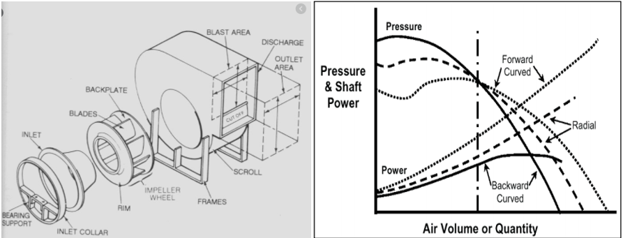
Centrifugal fans consist of an impeller in a casing with a spirally shaped contour, shown in Figure 1 (left side). The air enters the impeller in an axial direction and is discharged at the impeller’s outer periphery. The airflow moves along the centrifugal direction (or radial direction). Centrifugal fans can generate relatively high pressures, as compared with axial flow fans. For axial flow fans, the pressure rise is small, about be few inches of water.

Radial Fan and Static Pressure
Figure 1 Radial Fan and Static Pressure, Shaft Power V/s Volume Flow Curves for Different
Types of Blades

Generally, centrifugal fans have three types of blades: forward blade, backward blade, and radial blade. The characteristic curve of these three kinds of centrifugal fans is shown on the right side in Figure 1.

Sizing Using Cordier Diagram

Centrifugal fans (most turbomachines) can be classified based on specific speed (Ns) and specific diameters (Ds) as shown in Figure 2. Specific speed is a criterion at which a fan of unspecified diameter would run to give unit volume flow and pressure. The correlation for a specific speed and specific diameter can be seen here:

Pump Formula

where, ‘N’ is rotational speed (RPM), ‘Q’ is flow rate (ft3/sec), ‘H’ is head (ft), ‘D’ is diameter (ft) Read More

Considerations for Electric Aircraft Fan Design

Due to concerns about air travel’s impact on climate change, research and development into electric aircraft has been ongoing for several years. Within the last decade several startups as well as larger corporations have been developing electric or hybrid electric aircraft (Ros, 2017). The ultimate goal is to Conduct long (>500 miles), full-electric commercial flights with large aircrafts capable of carrying 100’s of passengers, but this will require at least 5-10 more years of development. Luckily, smaller electric aircraft designed for short-range flights (<500 miles) with anywhere from 1-20 passengers have already been tested successfully utilizing electric batteries, a hybrid-electric system and even a hydrogen fuel cell.  With these advances, emission-free air travel is closer than you think.

Electric Aircraft

Examples of full-electric aircraft designs include the Airbus E-Fan 1.0 and E-Fan 1.1 (Airbus Group), shown in Figure 1. These two-person aircraft utilize two ducted, variable-pitch fans, shown in Figure 2. Each fan is powered by a 30-kW electric motor. The motors are powered by several lithium-ion battery packs stored in the wings. While the aircraft only provides an hour of flight time, the batteries can recharge in approximately one hour and can be easily be swapped in and out.

Figure 1: Airbus E-Fan (Airbus Group)
Figure 2: E-Fan ducted fan (Varmin, 2014)

There are several reasons besides climate change why electric aircraft should be developed from a business perspective (Figure 3). Short and mid-range regional flights make up a significant portion of all flights around the world.  The current flight range of electric aircraft is limited to these short and mid-range fights. Additionally, shorter flights spend relatively more time taking off and landing than cruising at high altitudes, which makes shorter trips less energy efficient. While short, regional flights are economically unattractive for large commercial aircraft, a smaller aircraft with less fuel consumption may provide a valuable alternative. Read More

Considerations in Industrial Pump Selection

Pumps are machines that transfer liquids from suction to discharge by converting mechanical energy from a rotating impeller into what is known as head. The pressure applied to the liquid forces the fluid to flow at the required rate and to overcome frictional losses in piping, valves, fittings, and process equipment.

When it comes to pump selection, reliability and efficiency go hand-in-hand. Generally, a pump that has been selected and controlled properly for its normal operating points will operate near its best efficiency point (BEP) flow, with low forces exerted on the mechanical components and low vibration — all of which result in optimal reliability.

There are several factors like process fluid properties, end use requirements, environmental conditions, pump material, inlet conditions, and others which should be considered while selecting pumps for industrial applications. Selecting the right pump type and sizing it correctly are critical to the success of any pump application. Pumping applications include constant or variable flow rate requirements, serving single or networked loads, and consisting of open loops (nonreturn or liquid delivery) or closed loops (return systems).

Some crucial factors considered while pump selections include:

Fluid Properties: The pumping fluid properties can significantly affect the choice of pump. Key considerations include:

  • Acidity/alkalinity and chemical composition. Corrosive and acidic fluids can degrade pumps and should be considered when selecting pump materials.
  • Operating temperature: Pump materials and expansion, mechanical seal components, and packing materials need to be considered with pumped fluids that are hotter than 200°F.
  • Solids concentrations/particle sizes: When pumping abrasive liquids such as industrial slurries, selecting a pump that will not clog or fail prematurely depends on particle size, hardness, and the volumetric percentage of solids.
  • Specific gravity: It affects the energy required to lift and move the fluid and must be considered when determining pump power requirements.
  • Vapor pressure and Viscosity: Proper consideration of the fluid’s vapor pressure will help to minimize the risk of cavitation. High viscosity fluids result in reduced centrifugal pump performance and increased power requirements. It is particularly important to consider pump suction-side line losses when pumping viscous fluids.

­

Materials of Construction: It is always required to check the compatibility of materials of construction with the process liquid or any other liquids the pump might encounter. The initial cost of these materials is normally the first consideration. The operational costs, replacement costs and longevity of service and repair costs will, however, determine the actual cost of the pump during its lifetime. Charts are available to check the chemical compatibility and identify the most appropriate materials of construction for the pump.

The impact of the impeller material on the life of a pump under cavitation conditions is shown in Figure 1. As an example, changing from mild steel (reliability factor of 1.0) to stainless steel (reliability factor of 4.0) would increase the impeller life from cavitation damage by a factor of four. Hard coatings, such as certain ceramics, can also increase the impeller life under cavitating conditions.

Material Cavitation Life Factors
Figure 1 Material Cavitation life factors

Pump Sizing and Performance Specifications: The desired pump discharge is needed to accurately size the piping system, determine friction head losses, construct a system curve, and select a pump and drive motor. Process requirements can be achieved by providing a constant flow rate, or by using a throttling valve or variable speed drives. Read More

APPLICATION OF DIGITAL TWIN CONCEPT FOR SUPERCRITICAL CO2 OFF-DESIGN PERFORMANCE AND OPERATION ANALYSES

Update – February 28, 2023: AxCYCLE and AxSTREAM NET are our legacy software packages replaced by AxSTREAM System Simulation. System Simulation was born out of the union of the legacy AxCYCLE and AxSTREAM NET.

This is an excerpt from a technical paper, presented at the ASME Turbo Expo 2020 online conference and written by Leonid Moroz, Maksym Burlaka, Tishun Zhang, and Olga Altukhova. Follow the link at the end of the post to read the full study! 

Introduction

The attempts to simulate transient and steady-state sCO2 cycles off-design performance were performed by numerous authors [1], [2], [3], [4], and [5]. Some of them studied the dynamic behavior of regulators, some studied different control strategies or off-design behavior in different scenarios, which definitely has certain utility in the development of the reliable technology of sCO2 cycle simulation. Nevertheless, they used rather simplified models of components, especially turbomachinery and heat exchangers, which are of crucial importance to correctly simulate cycle performance.

The authors of this paper attempted to apply the digital twin concept to a simulation of off-design and part-load modes of the sCO2 bottoming cycle considering real machine characteristics and performance, which nobody tried to apply in this area.

On IGTC Japan 2015, SoftInWay Inc. has published a paper “Evaluation of Gas Turbine Exhaust Heat Recovery Utilizing Composite Supercritical CO2 Cycle”. The paper considered combinations of different bottoming sCO2 cycles for a specific middle power gas turbine. It mainly studied the advantages of different types of sCO2 cycles to increase the power production utilizing GTU waste heat.

The present paper is a further study based on that so the Cycle 2 [6] from that previous paper was selected as the sCO2 bottoming PGU layout in the present paper for subsequent analysis. The cycle is a combination of recompression cycle and simple cycle which offers 16.13 MW as output. GE LM6000-PH DLE gas turbine, was used as the heat source for bottoming PGU. According to GE official brochure [7], the GE LM6000 offers 40 MW to over 50 MW with up to 42% efficiency and 99% fleet reliability in a flexible, compact package design for utility, industrial and oil and gas applications. GE LM6000-PH DLE provides 53.26 MW output with exhaust temperature at 471 ℃ and exhaust flow at 138.8 kg/s. (This information came from GE products specification from 2015. It appears that GE continuously modifying the parameters of its turbines along with the naming of different modifications. Therefore, today’s parameters and configuration names might be slightly different comparing to 2015) Exhaust gas pressure was assumed to be 0.15 MPa. These parameters were taken to analyze the bottoming PGU and are presented below in TABLE 1.

SELECTED SET OF GE LM6000-PH DLE PARAMETERS
TABLE 1: SELECTED SET OF GE LM6000-PH DLE PARAMETERS

The digital twin (DT) concept is the developing technology that allows simulation of object behavior during its life cycle or in specified time due to changing ambient conditions, for example. The DT is applicable for performance tuning, digital machine building, healthcare, smart cities, etc [8] that allows decreasing the time and costs of development and optimize the object on the developing stage. GE has raised DT concepts for power plants to continually improves its ability to model and track the state of the plants [9].

In the context of this paper, DT is a simulation system comprised of physicist-based models organized in a special algorithmic structure that allows simulating the behavior of sCO2 PGU under alternating ambient conditions and grid demands.

The DT in this study was created utilizing AxSTREAM® Platform, which includes multiple software tools. The following software tools were utilized in this study: AxCYCLE™ was used to perform cycle thermodynamic calculation; solution generator in AxSTREAM® helped with finding possible machine geometry with given boundary conditions when performing preliminary design for compressors and turbines at design point; parameters and performance of turbomachinery including mass flow rate, pressure, power, efficiencies, etc. were calculated by Meanline/Streamline solver in AxSTREAM® for design and off-design conditions; AxSTREAM NET™ is a 1D system modeling solver and it was introduced here to simulate performance of heat exchangers (HEX) and pressure drop in the pipes involved in the cycle; AxSTREAM ION™ was used to integrate all modules and tools together in one simulation system. Read More

Pump Characteristic Curves

Update – March 1, 2023: AxSTREAM NET is our legacy software replaced by AxSTREAM System Simulation. System Simulation was born out of the union of the legacy AxCYCLE and AxSTREAM NET software packages.

Introduction

A pump is hardware that feeds energy to a fluid (e.g. Water) to flow through channels. Pumps are used, for example, to direct water out of the ground, to transport drinking or sewerage water over large distances in combined pipe networks or to discard water from polders. In any practical application, the pump needs to work with its best performance. It is also important to check that the flow rate and head of the pump are within the required specifications, which are normally presented as the Pump Characteristic curves. These plots play an important role in understanding the region in which the pump needs to be operated thus ensuring the life of the pump.

Pump Characteristic Curves

The performance of any type of pump can be shown graphically, which can be based on either the tests conducted by the manufacturer or the simulations done by the designer. These plots are presented as Pump Characteristic Curves. The hydraulic properties of any pump (e.g. Centrifugal Pump) can be described by the following characteristics.

  1. Q-H Curve
  2. Efficiency Curve
  3. Net Positive Suction Head (NPSH) Curve


Pump characteristic curves generated from AxSTREAM
Figure 1 Pump characteristic curves generated from AxSTREAM

Q-H Curve

The Q-H curve gives the relation between the volume flow rate and the pressure head, i.e. the lower the pump head, the higher the flow rate. Q-H curves are provided by the manufacturer of the pump and can normally be considered as simple quadratic curves.
Read More

The Simultaneous Simplicity and Complexity of Supersonic Turbines and their Modern Application

Supersonic axial turbines have attracted interest in the industry since the 1950s due to the high power they  provide, allowing a reduction in the number of low-pressure stages, and thus leading to lighter turbines as well as lower manufacturing and operational costs. Due to these valuable features, supersonic axial turbines are currently widely used in different power generation and mechanical drive fields such as rocket engine turbopumps [1, 2, 3, 4], control stages in high pressure multi-stage steam turbines, standalone single stage and 2-row velocity compound steam turbines [5, 6], ORC turbo-generator including geothermal binary power stations [7, 8, 9, 10], turbochargers for large diesel engines [11] and other applications. Therefore it is not forgotten, but instead a very important field in turbomachinery when highest specific power, compactness, low weight, low cost and ease of maintenance are dominant requirements. Especially nowadays, when development of small capacity reusable low-cost rocket launchers, compact and powerful waste heat recovery (WHR) units in the automotive industry, distributed power generation, and other fields are in extreme demand.

Meanline Results of Supersonic Turbine in AxSTREAM

Typically, supersonic turbine consists of supersonic nozzles with a subsonic inlet and one or two rows of rotating blades. The turbine usually has partial arc admission. The total flow could go through either a single partial arc or several ones. The latter is typical for a steam turbine control stage or standalone applications. The inlet manifold or nozzles chests, as well as exhaust duct, are critical parts of the turbine as well. Due to the very frequent application of partial admission, it is not possible to implement any significant reaction degree. Thus, this kind of turbine is almost always an impulse type. However, some reaction degree could still be applied to full admission turbines. The influence of  the rotor blades profile designed for high reaction degree on rotor-stator supersonic interaction and turbine performance is not well studied at the moment.

Read More

Compressors in Fuel Cell Systems

Previous Blog

As we covered in our previous blog about fuel cell systems, a large contributor to their efficiency is the compressor that is selected for it. But what are the different kinds of compressors, and which one is best for a specific system?

Compressors have a wide variety of designs and types, which differ in pressure and performance, depending on the kind of compressed fluid. Compressors are also classified according to the type of work: dynamic and positive displacement. Figure 1 shows the types and classification of compressors.

Figure 1 Compressor Types
Figure 1: Compressor Types. Source: Dongdong Zhao, “Control of an ultrahigh-speed centrifugal compressor for the air management of fuel cell systems” 5 Jun 2014, p. 8.

Figure 2 shows a comparison of various types of compressors according to several criteria: generated pressures, occupied volume, lubrication requirements, compressor weight, and pressure ripples at the outlet.

Comparisons of Compressors
Figure 2: Comparison of Compressors. Source: Dongdong Zhao, “Control of an ultrahigh-speed centrifugal compressor for the air management of fuel cell systems” 5 June 2014, p. 13.

As can be seen from the comparison above, we can conclude that centrifugal compressors offer a number of advantages over its positive displacement counterparts:

  1. Lightweight;
  2. Small volume;
  3. Only the bearings require lubrication;
  4. Creates a sufficiently high pressure (1.5…6 bar);
  5. Has high efficiency (80…82%); and
  6. Has a fairly wide performance range.

­

Next, we will consider the application of the centrifugal compressor in the fuel cell system. Read More

An Introduction to Fuel Cells: What Are They, How Do They Work, and How Can We Improve Their Efficiency?

Next Blog

Alternative energy based on the use of fuel cells is gaining more and more popularity and is increasingly being used in the automotive, aerospace, and energy industries as well as other sectors of the economy.

What is a Fuel Cell?

Fuel cells (FC) are electrochemical devices which convert the chemical energy of a fuel directly into usable energy – electricity and heat – without combustion. This is quite different from most electricity-generating devices (e.g., steam turbines, gas turbines, reciprocating engines), which first convert the chemical energy of a fuel to thermal energy via combustion, then into mechanical energy, and finally to electricity.

Fuel cells are similar to batteries containing electrodes and electrolytic materials to accomplish the electrochemical production of electricity. Batteries store chemical energy in an electrolyte and convert it to electricity on demand until the chemical energy has been depleted.

Fuel cells do not store chemical energy. Rather, they convert the chemical energy of a fuel into electricity. Thus fuel cells do not need recharging, and can continuously produce electricity as long as fuel and an oxidizer are supplied.

A prototype fuel cell is shown below in Figure 1.

Fuel Cell
Figure 1: Fuel Cell. Source

What is the operating principle of a fuel cell?

Today, there are two types of electrolytes used in fuel cells: acid or alkali. The type also depends on the chemical reactions that take place in the element itself. Read More

Performance Testing of Axial Compressors

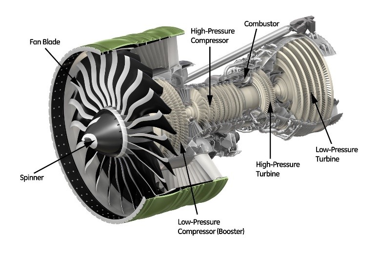
Performance testing is a key part of the design and development process of advanced axial compressors.  These are widely used in the modern world and can be found in nearly every industry, and include the core compressor for aeropropulsion turbofan engines, as well as aeroderivative gas turbine engines for power generation.  An example of this are the turbine engines shown in Figure 1 and 2, which feature an industrial gas turbine and a high bypass ratio turbofan engine with a multistage high-pressure core compressor. The development time of these machines can involve numerous expensive design-build-test iterations before they can become an efficient and competitive product. This places a great importance on the accuracy of the data taken during the performance tests during the development of the compressor since the test data taken is often used to anchor the loss models within the design tools. Modern axial compressors typically have high aerodynamic loadings per stage for improved system efficiency and requires precise aerodynamic matching of the stages to achieve the required pressure ratio with high efficiency. Variable geometry inlet guide vanes and stators in the first few stages are typically required to provide acceptable operability while maintaining high efficiency and adequate stall margin.

Industrial gas turbine for power generation.
Figure 1. Industrial gas turbine for power generation. Source
Figure 2. Turbofan engine for aeropropulsion.
Figure 2. Turbofan engine for aeropropulsion. Source

Performance Testing of Axial Compressors

Axial compressors all undergo a thorough design and development phase in which performance testing is vital to their ultimate success as a product. Performance testing during the development phase of these high-power density machines can ensure that the design meets the specified requirements or can identify a component within the turbomachine which falls short of its expected performance, and may require further development, and possible redesign. Performance testing can also ensure that the unit can meet all the conditions specified and not merely the guaranteed condition. Aerodynamic performance testing multistage axial compressors during the early part of development is often done in phases. The development test program is planned and executed with a design of experiments approach and includes varying the air flow and shaft rotational speed as well as the variable geometry schedule in order to fully characterize the compressor. In the first phase, the front block of the compressor is built and tested at corrected (referenced) air flow rate, inlet pressure, temperature and shaft rotational speed. Instrumentation includes utilizing traditional rakes and surveys at the exit, to obtain spanwise distributions of pressure, temperature, and flow angles. Testing in phases is typically done for two reasons. Read More