SoftInWay Inc. delivers time and cost saving turbomachinery solutions through industry-leading consulting services, fully in-house developed software, and customizable training courses.
We’ve done it! We have reached the finish-line for 2020, and by golly did it not come soon enough. Here at SoftInWay, the trials and tribulations brought on by the events of 2020 were felt, but thanks to the support of our partners, friends and customers, we were able to close out the year strong. So what did SoftInWay do this year?
Siemens Partnership
Right at the beginning of 2020, SoftInWay, Inc. officially entered a new partnership with Siemens Digital Industries. As SoftInWay has reigned as the turbomachinery master, we realize that turbomachinery component and system design is often part of a much greater system. As deadlines on projects become tighter, and project budgets decrease in the face of rising expenses, it has become more important than ever to have a streamlined workflow and toolset. Enter the SoftInWay/Siemens partnership. Thanks to this new enterprise, SoftInWay offers joint software solutions to mechanical engineering and turbomachinery companies. Industry standard tools like STAR-CCM+, Simcenter 3D, and NX CAD are now offered alongside the AxSTREAM platform. These gold-standard tools cover everything from component preliminary design to advanced heat transfer analysis, finite-element analysis, and CFD analysis, with results generated in a matter of hours. Read More
Update – March 1, 2023: AxSTREAM NET is our legacy software depreciated by AxSTREAM System Simulation. System Simulation was born out of the union of the legacy AxCYCLE and AxSTREAM NET software packages.
Bearings are very important machinery components since they dominate machine performance. Almost all machines and mechanisms with a rotating part, from the smallest motor to the largest power plants, from turbomachinery to reciprocating engines, and other industrial equipment our modern society relies upon, could not function without the use of bearings in some form. If one of the bearings fail, not only do the machines stop, but the assembly line also stops, and the resulting costs may be extremely high. For this reason, every bearing manufacturer makes every effort to ensure the highest quality for each bearing and that the end user subjects the bearing to careful use and properly maintains this component.
A bearing can be defined as a machine element which supports another moving machine element (known as a journal). It permits a relative motion between the contact surfaces of the members, while carrying the loads (static and dynamic). Some consideration will show that due to the relative motion between the contact surfaces, a certain amount of power is wasted in overcoming frictional resistance. If the rubbing surfaces are in direct contact, there will be rapid wear. In order to reduce frictional resistance, wear, and in some cases to carry away the heat generated, a layer of fluid (known as lubricant) may be provided. This lubricant is used to separate the journal and bearing, which allows the moving parts to move smoothly and helps to achieve more efficient machine operation. Some of the common bearing types are shown in Figure 1.
Figure 1. Common Types of Bearing Examples. SOURCE: [1]The main purpose of bearings is to prevent direct metal to metal contact between two elements that are in relative motion. This prevents friction, heat generation and ultimately, the wear and tear of parts. It also reduces the energy consumption required for moving parts. Additionally, they also transmit the load of the rotating element to the housing. This load may be axial, radial or a combination of both. Bearings also restrict the freedom of movement of moving parts to a predefined direction. With all these aspects, bearings are clearly important for the operations and the reliability of mechanical products. The right bearing can increase useful life of the machine, and enhance the machine’s overall performance. The wrong bearing can lead to premature failure, increased downtime, and increased wear and fatigue among all components of the machine. Read More
As a special tribute this Veterans Day, we decided to have a look at some of the most notable engines that have been used to propel military vehicles throughout history.
PW F135
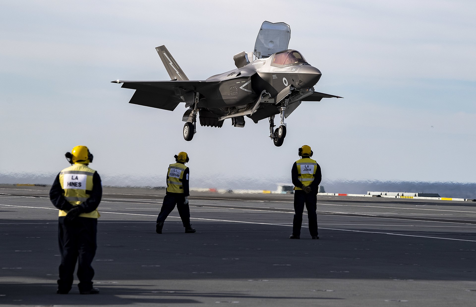
Kicking off our list is the Pratt & Whitney 135 turbofan engine. The pride and joy of Pratt & Whitney’s military engine lineup, the 135 powers the US Military’s F35 Lightning II. Presently, two variants of the F135 are used in several different variants of the F35, although it should be noted that the F135 was developed specifically for the F35. The 3 engine variants are known as the F135-PW-100, the F135-PW-600, and the F135-PW-400, each for a different application of the F35. The 100 variant is used in the conventional take off and landing F35A, the 600 is used in the F135B for short take off and vertical landing F35B, and the 400 uses salt corrosion-resistant materials for the Naval variant F35C.
A Lockheed Martin F35A in fight, and an F35C taking off from the USS Abraham Lincoln
The F135 is capable of 28,000 lbf of thrust with the afterburner capability pushing thrust all the way to a whopping 43,000 lbf of thrust, making the Lightning II a supersonic STOVL aircraft suited to a wide variety of applications, as seen in the above illustrations. At the heart of the Pratt F135 are 3 fan stages, 6 compressor stages, and 3 turbine stages. In the STOVL variant, the F135-600 uses the same core components, but is also coupled to a drive shaft which connects the engine to the lift fans which were originally developed by Rolls-Royce, and give the Lightning the ability to hover, perform short distance takeoffs, and vertical landings.
A Royal Air Force RAF F35B Lightning II performing a vertical landing on a Royal Navy carrier.
The F35 by Pratt & Whitney and in turn the F35 Lightning II by Lockheed Martin represent the cutting edge in military aviation, and are the centerpieces of Pratt and Lockheed respectively. The Lightning variants and this line of turbofan engines will be in service with several branches of the US military and its allies around the world for the foreseeable future, with more iterations of the F135 to come. Read More
Update – March 1, 2023: AxSTREAM NET is our legacy software depreciated by AxSTREAM System Simulation. System Simulation was born out of the union of the legacy AxCYCLE and AxSTREAM NET software packages.
Even in today’s age of underwater nuclear power, the majority of the world’s submarines still use diesel engines as their main source of mechanical power, as they have done since the turn of the century. A diesel engine must operate at its optimum performance to ensure a long and reliable life of engine components and to achieve peak efficiency. To operate or keep running a diesel engine at its optimum performance, the correct lubrication is required. General motors V16-278A type engine is normally found on fleet type submarines and is shown in Figure 1. This engine has two banks of 8 cylinders, each arranged in a V-design with 40 degree between banks. It is rated at 1600 bhp at 750 rpm and equipped with mechanical or solid type injection and has a uniform valve and port system of scavenging[1].
Figure 1. GM V16-278A, Submarine Diesel Engine. SOURCE: [1]Lubrication system failure is the most expensive and frequent cause of damage, followed by incorrect maintenance and poor fuel management. Improper lubrication oil management combined with abrasive particle contamination cause the majority of damage. Therefore, an efficient lubrication system is essential to minimize risk of engine damage.
The purpose of an efficient lubrication system in a submarine’s diesel engine is to:
Prevent metal to metal contact between moving parts in the engine;
Aid in engine cooling by removing heat generated due to friction;
Form a seal between the piston rings and the cylinder walls; and
Aid in keeping the inside of the engine free of any debris or impurities which are introduced during engine operation.
All of these requirements should be met for an efficient lubrication system. To achieve this, the necessary amount of lubricant oil flow rate with appropriate pressure should circulate throughout the entire system, which includes each component such as bearings, gears, piston cooling, and lubrication. If the required amount of flow rate does not flow or circulate properly to each corner of the system or rotating components, then cavitation will occur due to adverse pressure and excessive heat will be generated due to less mass flow rate. This will lead to major damage of engine components and reduced lifetime. Read More
The release of combustible gas during the interaction of metals and acids was observed as early as the 16th century. That is, during the formation of chemistry as a science. The famous English scientist Henry Cavendish had studied the substance since 1766, and gave it the name “combustible air”. When burned, this gas produced water. Unfortunately, the scientist’s adherence to the theory of phlogiston (the theory that suggested the existence of a fire-type element in materials) prevented him from coming to the correct conclusions.
In 1783 the French chemist and naturalist A. Lavoisier, together with the engineer J. Meunier, and with the help of special gas meters carried out the synthesis of water, and then its analysis by means of decomposition of water vapor with hot iron. Thus, scientists were able to come to the correct conclusions, and dismantle the phlogiston theory. They found that “combustible air” is not only a part of water but can also be obtained from it. In 1787, Lavoisier put forward the assumption that the gas under study is a simple substance and, accordingly, belongs to the number of primary chemical elements. He named it hydrogene (from the Greek words hydor – water + gennao – I give birth), that is, “giving birth to water”.
In a free state and under normal conditions, hydrogen is a gas, and is colorless, odorless and tasteless. Hydrogen has almost 14.5 times mass less than air. It usually exists in combination with other elements, such as oxygen in water, carbon in methane, and organic compounds. Because hydrogen is chemically extremely active, it is rarely present as an unbound element. Read More
Update – March 1, 2023: AxSTREAM NET is our legacy software depreciated by AxSTREAM System Simulation. System Simulation was born out of the union of the legacy AxCYCLE and AxSTREAM NET software packages.
INTRODUCTION
In the aircraft industry, several systems are designed to provide safety and comfort for crew and passengers while traveling. Oxygen gets rarified with altitude, so life support is a very important system
The cabin is pressurized in order to provide breathable air, but reaching a sea level pressure is not advisable since it would lead to a significant pressure differential between the aircraft exterior and the cabin interior. This difference could damage the aircraft structure.
Additionally, the cabin altitude is different from the flight altitude. In fact, the cabin altitude corresponds to the one reached according to the cabin pressure. Usually a commercial flight cruises at an altitude of 35,000 ft, but thanks to the pressurization system, the cabin altitude is around 6,000-8,000 ft. Indeed, the oxygen system provides breathable oxygen to the crew and passengers if any problem were to occur during the flight.
AIRCRAFT EMERGENCY OXYGEN SYSTEM:
In a normal situation, a bleed air system is used to provide fresh air throughout the flight duration. The air is hot and must be cooled and pressurized to make it breathable. In the event of an emergency, the plane is already equipped with oxygen systems which are linked to passengers and cabin crew through masks. In fact, there are two oxygen systems on board. One designed for the crew, and the second for the passengers.
If the cabin pressure drops making cabin altitude about 14,000 ft, the emergency system are be triggered. The emergency system provides oxygen to passengers for 15 to 20 minutes, and for the crew members for around 30 minutes. This is enough time for the aircraft to descend to a lower altitude and being the cabin altitude to a safe breathable level.
Here, the crew oxygen system schematic of the Boeing 737 class is shown in Figure 1.
Figure 1-Crew oxygen system
The main challenges of oxygen equipment are:
Fitting the dimensions of the plane
Secure (no leakage for example)
Responsive (to cabin pressure and cabin altitude)
Easy for passengers to use the oxygen system through the deployed masks quickly, before the effects of altitude are felt:
At 25,000 ft: a person has 3 minutes of consciousness
At 41,000 ft: a person has 30 seconds of consciousness
FLIGHT CREW OXYGEN
The flight crew oxygen should be designed and made with a lot of care, because if any trouble occurs during the flight, the crew must be able to handle the situation and take the airplane and its passengers down safely. Read More
Hello! And welcome back for part 2 of our series on “A Brief History of the Turbocharger”. To read part 1, which compares superchargers and turbochargers, and explains the early history of turbochargers and forced induction from the turn of the century through to World War 1, click here. Having covered all of that, let’s pick up from where we left off!
Following World War 1, and the work of Dr. Sanford Alexander Moss, Alfred Büchi, who had created the first true turbocharger, had continued innovating following the failure of his first design. By 1925, he had a working turbocharger design that consistently and reliably worked (1).
Following this breakthrough, the turbocharger saw its first commercial application on ten-cylinder diesel engines. Since diesel engines are typically built to withstand the high-pressures required by their operating conditions, the pressures generated by using forced induction are easily accommodated. As a result of adding the turbochargers, the engines upped their horsepower ratings from 1750HP, all the way to a whopping 2,500HP. (1)
The Hansestadt Danzig, one of the German ships fitted with the 10 cylinder turbodiesel engine described above. (shipspotting.com)
For Büchi, this was a great achievement, as it marked the first commercial application of a machine that he had first begun working with more than 20 years prior. For the turbocharger, however, this was just the beginning. Read More
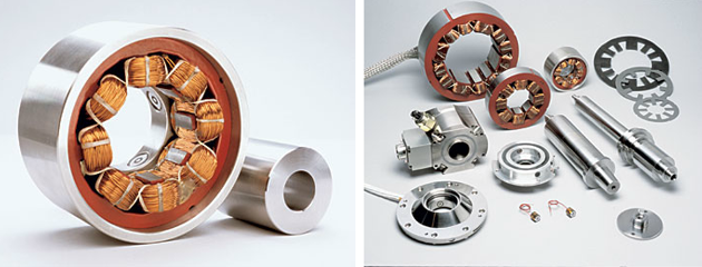
From the beginning of the turbomachinery era, in the 19th century, engineers have been thinking about ways to reduce losses in rotating machines. Losses connected with fluid motion or producing the useful effects are related to the main purpose of machine operation,while losses in rotor bearings are just annoying and inevitable. Fluid film and rolling element bearings are effective solutions, but their operational principles cause increased friction – the best predictor of losses. But what if we could reduce the losses in rotating machines by avoiding the friction in required supports? What if a rotor could levitate and rotate in the air held by some magic forces? And furthermore, what if this magic could give us even bigger dividends, for example, enabling variable stiffness of rotor supports and safe passing through resonances? Luckily, engineers have already invented how to turn this magic into reality with active magnetic bearings.
The early patents of active magnetic bearings principles were recorded during the World War II, but the decisive breakthrough in production and applications of them were made during the the last three decades when the latest research about the active magnetic bearing operation and control made utilization feasible and economically viable [1].
The early patents of active magnetic bearings principles were recorded during the World War II, but the decisive breakthrough in production and applications of them were made during the the last three decades when the latest research about the active magnetic bearing operation and control made utilization feasible and economically viable [1].
Active Magnetic Bearing and its Components [2]The main idea of an active magnetic bearing is based on the electromagnetic processes. Electrical current passing through densely wound copper coils creates magnetic fields which interact with a magnetized sleeve connected to the rotor.
Sounds pretty simple, right? But why on Earth did it take so much time to go from the general ideas to a real industrial application of active magnetic bearings? Read More
Update – March 1, 2023: AxSTREAM NET is our legacy software depreciated by AxSTREAM System Simulation. System Simulation was born out of the union of the legacy AxCYCLE and AxSTREAM NET software packages.
Through the decades, the aircraft industry always improved their onboard systems to get the best performances, security and comfort. In order to build a lasting travel type, security of the aircraft is one of the main goals for engineers. Due to rough exterior conditions while flying, especially at high altitude, with relative humidity and very low temperatures, the freezing temperature can cause the plane to ice. Ice can have major impacts on the aircraft’s weight and aerodynamical phenomena, – especially the lift – (the lift can decrease to 40% due to ice). Modeling and installing a specific system to prevent ice is a necessity. Therefore, aircraft designers developed an anti-icing system inside the wing to prevent ice.
There are several anti-icing systems on aircraft, mostly depending of the engine’s type. Most of aircrafts use the bleed air system, which consists of using a hot bleed air to warm up the wing leading edge. Another system named de-icing boots system is mostly used on turboprop aircrafts and consists of black rubbers at locations prone to icing which inflate and literally break the ice. Another system is simply an electrical leading edge warm up directly installed in the wing leading edge. Those examples are just an introduction to some anti-icing systems that aircraft industry has develop and are using. Each have pros and cons.
Here, we will focus on the anti-icing system using hot bleed air. This approach is used by the Boeing 737-300/400/500 anti-icing system with hot bleed air warming the leading edges.
Typically, this type of anti-icing system consists of a hot bleed air flow provided by the engine compressor’s stages to warm up the plane’s wing leading edge. The wing anti-icing system is made of two independent pneumatic systems among others, providing hot bleed air from each of the two turbofans separately. The hot bleed air is ducted via the engine bleed valve from the fifth compressor stage. If the pressure isn’t enough, bleed from the ninth compressor stage can additionally be used. Note that the fifth stage bleed air temperature is approximately 340°C and the ninth stage one is approximately 540°C which are too hot to be used in aircraft’s pneumatic systems such as hydraulic pressurization or potable water system pressurization for example. The hot air then runs through a pre-cooler to reduce the temperature to 200°C and this cooled air is distributed via the bleed ducts to consumers like the air conditioning packs for example and the wing anti-icing system. In order to know the moment to use the anti-icing system, the aircraft’s pilots use the visual ice indicator which is situated in the middle beam of the window. Once the probe is icing, the pilots enable the anti-icing system. Hence, hot bleed air is provided to the slates number three, four and five as shown in Figure 1.
Figure 1 – Leading Edge Slats
Due to the larger diameter and the aerodynamics phenomena, slates number one and two do not need any anti-icing devices. Once the anti-icing system is enabled, the hot bleed air is guided along telescopic pipes then is distributed via piccolo tubes as shown in Figure 2. From there, it exits the piccolo tubes through little holes, warms the wing leading edge and flows out of the wing through exit holes situating on the wing’s lower surface. Read More
Update – March 1, 2023: AxSTREAM NET is our legacy software depreciated by AxSTREAM System Simulation. System Simulation was born out of the union of the legacy AxCYCLE and AxSTREAM NET software packages.
The development of fuel cell technologies and improvements in fuel cells power densities combine to make the use of fuel cells possible in different power sectors as primary or secondary power sources for commercial purpose, residential power requirements, and automobiles, etc. The fuel cell harnesses the chemical energy of a fuel along with an oxidizing agent by converting it into electrical energy through a pair of reactions. For example, in a hydrogen fuel cell, as shown in Figure 1, the hydrogen combines with oxygen from the air to produce electricity and releases water.
Figure 1 Fuel Cell System [1]The design of a fuel cell system is quite complex and depends on fuel cell types and their applications. With so many possible combinations of fuel cells, this article will not focus on different type of fuel cells, but on Air Management Systems which may significantly affect the overall performance of a fuel cell system.
Air Management Systems
Key sub-systems of any fuel cell system are the fuel processor, fuel cell stack, air management and power management systems. The air management system strongly affects the fuel cell stack efficiency and the power loss of the fuel cells. Therefore, it is necessary to develop a clean, reliable, cost-effective oil-free air system [2].
Major tasks in air management system are Air Supply, Air Cleaning, Pressurization and Humidification. Read More
We use cookies on our website to give you the most relevant experience by remembering your preferences and repeat visits. By clicking “Accept”, you consent to the use of ALL the cookies.
This website uses cookies to improve your experience while you navigate through the website. Out of these, the cookies that are categorized as necessary are stored on your browser as they are essential for the working of basic functionalities of the website. We also use third-party cookies that help us analyze and understand how you use this website. These cookies will be stored in your browser only with your consent. You also have the option to opt-out of these cookies. But opting out of some of these cookies may affect your browsing experience.
Necessary cookies are absolutely essential for the website to function properly. These cookies ensure basic functionalities and security features of the website, anonymously.
Cookie
Duration
Description
cookielawinfo-checkbox-analytics
11 months
This cookie is set by GDPR Cookie Consent plugin. The cookie is used to store the user consent for the cookies in the category "Analytics".
cookielawinfo-checkbox-functional
11 months
The cookie is set by GDPR cookie consent to record the user consent for the cookies in the category "Functional".
cookielawinfo-checkbox-necessary
11 months
This cookie is set by GDPR Cookie Consent plugin. The cookies is used to store the user consent for the cookies in the category "Necessary".
cookielawinfo-checkbox-others
11 months
This cookie is set by GDPR Cookie Consent plugin. The cookie is used to store the user consent for the cookies in the category "Other.
cookielawinfo-checkbox-performance
11 months
This cookie is set by GDPR Cookie Consent plugin. The cookie is used to store the user consent for the cookies in the category "Performance".
viewed_cookie_policy
11 months
The cookie is set by the GDPR Cookie Consent plugin and is used to store whether or not user has consented to the use of cookies. It does not store any personal data.
Functional cookies help to perform certain functionalities like sharing the content of the website on social media platforms, collect feedbacks, and other third-party features.
Performance cookies are used to understand and analyze the key performance indexes of the website which helps in delivering a better user experience for the visitors.
Analytical cookies are used to understand how visitors interact with the website. These cookies help provide information on metrics the number of visitors, bounce rate, traffic source, etc.
Advertisement cookies are used to provide visitors with relevant ads and marketing campaigns. These cookies track visitors across websites and collect information to provide customized ads.


![Figure 1. Common Types of Bearing Examples. SOURCE: [1]](https://blog.softinway.com/wp-content/uploads/2020/12/Figure-1.-Common-Types-of-Bearing-Example.jpg)

![Figure 1. GM V16-278A, Submarine Diesel Engine. SOURCE: [1]](https://blog.softinway.com/wp-content/uploads/2020/11/GM-V16-278A-Submarine-Diesel-Engine.png)