SoftInWay Inc. delivers time and cost saving turbomachinery solutions through industry-leading consulting services, fully in-house developed software, and customizable training courses.
Update – March 1, 2023: AxCYCLE is our legacy software depreciated by AxSTREAM System Simulation. System Simulation was born out of the union of the legacy AxCYCLE and AxSTREAM NET software packages.
Supercritical carbon dioxide cycles have slowly become more popular in the engineering market for electricity generation from various sources. SCO2 is found to be an ideal working fluid for generating power cycles due to its high efficiency –more than supercritical or superheated steam, which results in lower cost of electricity.
Supercritical carbon dioxide is a fluid state where carbon dioxide is operated above its critical point which causes the compound to behave as both a gas and a liquid simultaneously with the unique ability to flow as a gas though at the same time dissolve materials like a liquid. SCO2 changes density over small difference in temperature or pressure, though stay in the same phase; allowing large amount of energy to be extracted at higher temperatures.
Update – March 1, 2023: AxCYCLE is our legacy software depreciated by AxSTREAM System Simulation. System Simulation was born out of the union of the legacy AxCYCLE and AxSTREAM NET software packages.
The design of a boiler feed pump turbine features some unique characteristics that presents certain challenges in terms of efficiency management, varying operating ranges, and many other features. In order better understand the accepted designs of Boiler Feed Pump Turbines (BFPTs), it is important to know how the operation of steam turbines used to drive boiler feed pumps can fundamentally improve fossil and nuclear plants. Much like the design of mechanical drive turbines, feed pump turbines also feature the same thermodynamic objectives as the main turbine and all of the engineering difficulties with optimal blade design, rotor and bearing harmonic conditions, ideal flow path definitions, and so on. However, some distinctions can make a BFPT design particularly distinct from a regular mechanical drive turbine. Figure 1 shows a basic heat balance diagram for a plant using a boiler feed pump turbine arrangement.
Figure 1 – Simple Process Diagram for Plant with Boiler Feed Pump Turbine in AxCYCLE®
Inherent in its name, the BFPT must be fully compatible with the boiler feed pump. In other words, the necessary power and speed of the BFPT are determined by the requirements of the pump. In a fully integrated and dynamic system such as this, a large portion of the design requires developing a proper heat balance that will optimize the plant performance. In general, the boiler feed pump turbine uses both steam from the boiler and the main turbine to drive the mechanical shaft connected to the boiler feed pump. This arrangement has proven highly successful in efficiently applying the steam’s thermal energy throughout the plant. In certain arrangements, the BFPT can instead accept steam from cold reheat lines, main unit crossover piping lines, and different extractions from the main turbine. Regardless of the source, one distinction specifically unique to the BFPT is that it must accept steam from two separate sources.
Update – March 1, 2023: AxSTREAM NET is our legacy software depreciated by AxSTREAM System Simulation. System Simulation was born out of the union of the legacy AxCYCLE and AxSTREAM NET software packages.
In an internal combustion engine, combustion of air and fuel takes place inside the engine cylinder and hot gases are generated with temperature of gases around 2300-2500°C which may result in not only burning of oil film between the moving parts, but also in seizing or welding of the stationery and moving components. This temperature must be reduced such that the engine works at top efficienc, promoting high volumetric efficiency and ensuring better combustion without compromising the thermal efficiency due to overcooling. Most importantly, the engine needs to function both in the sense of mechanical operation and reliability. In short, cooling is a matter of equalization of internal temperature to prevent local overheating as well as to remove sufficient heat energy to maintain a practical overall working temperature.
It is also important to note that about 20-25% of the total heat generated is used for producing brake power (useful work). The cooling system should be designed to remove 30-35% of total heat and the remaining heat is lost in friction and carried away by exhaust gases.
Geothermal energy has become more and more popular globally due to its sustainability and economic stand point. Geothermal power plants run on a variety of temperatures and utilize hydrothermal resources (water/steam and heat) from below the earth surface to generate electricity for people’s daily consumption. Resources can come from dry steam or hot water wells.
There are three kinds of Geothermal cycle for power plants: binary cycle, dry steam and flash steam. Binary cycle power plants use the heat transfer from geothermal hot water to secondary fluids with a low boiling point at the lower end of standard geothermal temperature (225 to 360 F). This heat will cause the secondary fluid to bubble and turn into steam in the heat exchanger, which is then used to turn the turbine. Since water and secondary fluids are kept apart in the cycle, air emission is minimized.
Turboexpanders are used in a number of applications, including floating LNG (liquefied natural gas), LPG (liquefied petroleum gas) / NGL (natural gas liquids), dew point control, and ethylene plants. Used as a highly efficient system that takes advantage of high pressure, high-temperature flows, the turboexpander both produces cryogenic temperatures and simultaneously converts thermal energy into shaft power. Essentially, a turboexpander is comprised of a radial inflow expansion turbine and a centrifugal compressor combined as a single unit on a rigid shaft. The process fluid from a plant stream will run through the expansion turbine to both provide low-temperature refrigeration and convert thermal energy to mechanical power as a byproduct. First, the gas will radially enter the variable inlet nozzles (or guide vanes) of the turbine, which will allow for a localized increase in fluid velocity prior to entering the turbine wheel. The turbine wheel will accept this high-temperature, high-pressure, accelerated gas and convert it into mechanical energy via shaft rotation. The primary product of a turboexpander manifests at the outflow of this turbine. After the process gas passes through the turbine wheel, this gas has expanded so dramatically that it produces cryogenic temperatures colder than any other equipment in the plant.
The useful mechanical energy converted from this system is generally used to drive a centrifugal compressor positioned on the opposite end of the shaft. In the case of this expander-compressor setup, the mentioned turboexpander technology avoids the excessive use of fuel consumption seen in other systems, and significantly decreases the CO2 footprint of the overall design. As well, there are various examples of turboexpanders that use an expander-generator setup, which converts the mechanical energy from the turbine into direct electrical power. Turboexpanders have come a long way in the last 40 years. With the advent of magnetic bearings and more advanced sealing systems, turboexpanders have been able to handle shaft speeds in large and small machines of up to 10,000 rpm and 120,000 rpm, respectively. Moreover, innovations in specific CFD modules for turbomachinery have allowed turboexpander systems to achieve efficiencies upwards of 90%.
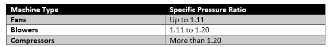
Many people speculate about the confusion on what is considered a compressor, a blower, or simply a fan. In essence, each of these turbo-machines achieve a pressure rise by adding velocity to a continuous flow of fluid. The distinctions between fans, blowers, and compressors are quite simply defined by one parameter, the specific pressure ratio. Each machine type, however, utilizes a number of different design techniques specific to lower and higher-pressure applications. As per the American Society of Mechanical Engineers (ASME), the specific pressure is defined as the ratio of the discharge pressure over the suction pressure (or inlet pressure). The table shown below defines the range at which fans, blowers, and compressors are categorized.
Similarities between the design of fans and blowers occur near the lower end of a blower’s range. As well, many design parallels exist between high-pressure blowers and compressors. For the article, we will be investigating the different design characteristics of centrifugal blowers. Blower selection depends on a number of factors including operating range, efficiency, space limitations, and material handled. Figure 1 shows a number of different impeller blade designs that are available for centrifugal blowers.
Existing research studies for the corresponding flow-induced vibration analysis of centrifugal pumps are mainly carried out without considering the interaction between fluid and structure. The ignorance of fluid structure interaction (FSI) means that the energy transfer between fluid and structure is neglected. To some extent, the accuracy and reliability of unsteady flow and rotor deflection analysis should be affected by this interaction mechanism.
In recent years, more and more applications of FSI are found in the reliability research of turbomachinery. Most of them are about turbines, and a few of them address pumps. Kato [1] predicted the noise from a multi-stage centrifugal pump using one-way coupling method. This practical approach treats the fluid physics and the solid physics consecutively.
For the majority of pump application, the growing use of variable speed operation has increased the likelihood of resonance conditions that can cause excessive vibration levels, which can negatively impact pump performance and reliability. Mechanical resonance is the tendency of a mechanical system to absorb more energy when the frequency of its oscillations (external excitation source) matches the system’s natural frequency of vibration more than it does at other frequencies. To avoid vibration issues, potential complications must be properly addressed and mitigated during the design phase.
Some of the factors that may cause excitation of a natural frequency include rotational balance, impeller exit pressure pulsations, and gear couplings misalignment. The effect of the resonance can be determined by evaluating the pumping machinery construction. All aspects of the installation such as the discharge head, mounting structure, piping and drive system will affect lateral, torsional and structural frequencies of the pumping system. It is advised that the analysis be conducted during the initial design phase to reduce the probability of reliability problems and the time and expense associated.
The integrally geared compressor, also known as a multi-shaft compressor, is a technology that has been around since the 1960s, but remains underdeveloped. Usually seen in applications in the industrial gases industry, integrally geared compressors (IGCs) can range in size from small product machines to steam turbine driven high-horsepower, high-flow compressors for air separation plants. These compressors modular construction principle, consisting of as many as eight different stages, allows for implementation in a large number of varied customer processes. The main advantages of IGCs in the industrial gases industry is the compact design and smaller installation footprint, efficiency increases due to the use of multiple speeds for separate impellers, and overall lower operational and installation costs.
Figure 1 – Semi-Open Impeller
One of the key design differences between the standard inline compressors and the IGCs is that the integrally geared compressor makes use of both closed AND semi-open impellers. The reason for the use of open impellers in IGCs are the higher strengths due to better manufacturing techniques, speed of manufacture, and the inherent lower costs. However, the main drawback to having an open impeller in your system is that in the event of impeller rub, the damage to the compressor would be significantly worse than with a closed impeller.
When designing rotating equipment, it is extremely important to take into account the types of unbalance that can occur. Forgetting this step can result in vibrations that lead to damage of the rotating parts, increasing maintenance costs and lowering efficiency. Currently, if a rotating part already vibrates or makes any noises, maintenance engineers rely on OEMs (Original Equipment Manufacturer) or third parties services companies to conduct balancing services.
Types of Unbalances
Figure 1: Static and Couple Forms of Unbalance
The three types of unbalances to consider are static, couple and dynamic. Static unbalance (Figure 1) occurs when a mass at a certain radius from the axis of rotation causes a shift in the inertia axis. Couple unbalance, usually found in cylindrical shapes, occurs when two equal masses positioned at 180 degrees from each other cause a shift in the inertia axis, leading to vibration effects on the bearings. Lastly and most common, dynamic unbalance occurs when you have a combination of both static and couple unbalance.
We use cookies on our website to give you the most relevant experience by remembering your preferences and repeat visits. By clicking “Accept”, you consent to the use of ALL the cookies.
This website uses cookies to improve your experience while you navigate through the website. Out of these, the cookies that are categorized as necessary are stored on your browser as they are essential for the working of basic functionalities of the website. We also use third-party cookies that help us analyze and understand how you use this website. These cookies will be stored in your browser only with your consent. You also have the option to opt-out of these cookies. But opting out of some of these cookies may affect your browsing experience.
Necessary cookies are absolutely essential for the website to function properly. These cookies ensure basic functionalities and security features of the website, anonymously.
Cookie
Duration
Description
cookielawinfo-checkbox-analytics
11 months
This cookie is set by GDPR Cookie Consent plugin. The cookie is used to store the user consent for the cookies in the category "Analytics".
cookielawinfo-checkbox-functional
11 months
The cookie is set by GDPR cookie consent to record the user consent for the cookies in the category "Functional".
cookielawinfo-checkbox-necessary
11 months
This cookie is set by GDPR Cookie Consent plugin. The cookies is used to store the user consent for the cookies in the category "Necessary".
cookielawinfo-checkbox-others
11 months
This cookie is set by GDPR Cookie Consent plugin. The cookie is used to store the user consent for the cookies in the category "Other.
cookielawinfo-checkbox-performance
11 months
This cookie is set by GDPR Cookie Consent plugin. The cookie is used to store the user consent for the cookies in the category "Performance".
viewed_cookie_policy
11 months
The cookie is set by the GDPR Cookie Consent plugin and is used to store whether or not user has consented to the use of cookies. It does not store any personal data.
Functional cookies help to perform certain functionalities like sharing the content of the website on social media platforms, collect feedbacks, and other third-party features.
Performance cookies are used to understand and analyze the key performance indexes of the website which helps in delivering a better user experience for the visitors.
Analytical cookies are used to understand how visitors interact with the website. These cookies help provide information on metrics the number of visitors, bounce rate, traffic source, etc.
Advertisement cookies are used to provide visitors with relevant ads and marketing campaigns. These cookies track visitors across websites and collect information to provide customized ads.